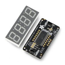
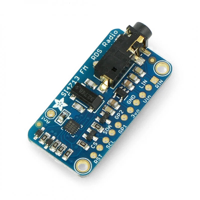
Si4713 - FM stereo radio transmitter with RDS/RBDS - Adafruit 1958
- Артикул:
- 47897777


Характеристики
Прочие свойства
- Бренд
- Adafruit
Описание
A radio transmitter operating on FM waves basing on the high-class Si4713 system. The device transmits within a radius of up to 10 m, it communicates via I2C interface, it works with a voltage from 3 V to 5 V. It also allows for the RDS / RBDS data to be transmitted and has a soldered audio Jack connectors which allow you to connect the transmitted audio signal.
The product is compatible with Arduino
Sample code can be found inthe user guide.
For receiving the signal transmitted through the transmitter of audio signal and of RDS / RBDS data, sufficient is just any radio receiver operating in the FM band, for example, in a car radio.
Connection
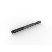
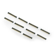
The set includesgoldpinconnectors,pitch of 2.54mm and the transmitting wire which must be self-soldered. The description of the individual pins are presented in the form of a table:
Pin Description VIN Supply voltage in the range from 3 V to 5 V. GND The ground of the system. 3Vo 3.3 V voltage regulator's output with the maximum current of up to 100 mA LIN Left audio channel - connected to the audio jack slot, it enables to connect the transmitted audio signal. RIN Right audio channel - connected to the audio jack, it enables to connect the transmitted audio signal. RST The reset is activated with the low status. The manufacturer recommends the reset of the system before starting the communication with the microcontroller. CS In the SPI mode, it is a chip select. For I2C, it is the choice of the bus address, by default, in a high status, it sets the address to 0x63. Indicating the low status, changes the address to 0x11. SCL Clock line of I2C interface. SDA Data line of I2C interface. GP1 Additional GPIO pin, which works with a voltage of 3.3 V. Be careful not to short the pin from GND or VCC at the start of the module. GP2 Additional GPIO pin is working with a voltage of 3.3 V. Be careful not to short the pin from GND or VCC at the start of the module.
Specification
- Controller: Si4712 (documentation)
- The transmitter operates in the FM band, it also sends the data to the RDS/RBDS
- Built-in audio jack 3,5 mm slot which allows you to connect transmitted audio signal.
- The set also includes a transmitting cable andthe goldpin connectorsfor self-soldering
- Board dimensions: 38 x 19 x 2 mm
- Weight: approx 3.5 g
Useful links
- The website of the manufacturer: Adafruit 1958
- User manual
- Si4712 system documentation
- The scheme and design files