Tic T249 - USB stepper motor driver 47V/4,5A - Pololu 3139
- Артикул:
- 42766919


Характеристики
Общие характеристики
- Напряжение до
- 10.0 V
- Напряжение от
- 47.0 V
Прочие свойства
- Бренд
- Pololu
Свойства
- Каналы
- 1
Энергопитание
- Сила тока
- 4.5 A
Описание
The system allows you to control the stepper motor using a device that allows you to generate logical states, such as Arduino, STM32Discovoery, RaspberryPior anymicrocontroller. The driver can be configured, tested and monitored via USB, runs on Windows, Linux, and macOS.
The Polol module is characterized by very simple operation. To rotate the engine one step at a time,the STEP outputmustbe given a high state (logical one), the next sequence of zeroes and ones will move the engine one step at a time, and so on. The direction is selected by entering the appropriate state on the DIR output (e.g. low state - clockwise rotation, high state - the opposite). The controller also has the ability to select the resolution of the motor.
Connecting the controllerTo control the bipolar stepper motor, connect the system as shown in the figure below. If the nominal motor voltage is lower than the required power supply for the controller (10 V), set the current limit manually using a potentiometer.
The figure shows the minimum controller connection
The manufacturer provides a comprehensiveuser guide.
Power supplyA5-volt controller is required for power supply (no external logic power supply is required), which must be led to a 5-volt pin.Themotor supply voltage from 10 V to 47 V is fed to the VIN pin.The systemcan control motors with a nominal voltage lower than the required 10 V. For this purpose, the maximum current consumption must be limited by means of a potentiometer so as not to exceed the permitted motor current. For example, for a motor with a resistance of 5 Ω per coil and a current consumption of 1 A, the nominal supply voltage is 5 V. When supplying 12 V, the current should be limited so that it does not exceed 1 A.
Attention!
Connecting and disconnecting the motor while the controller is on can damage the system.
LEDsThere are three LEDs on the board: green, red, yellow. Green indicates communication via USB. Red is associated with the ERR pin, if it lights up it indicates an error. Yellow indicates the status of the stepper motor and gives some information about errors, if any. For a detailed description see thedocumentation on the manufacturer's website.
Heat dissipationThe plate is designed to dissipate heat at a current consumption of approximately 1.8 A per coil. If the current is much higher, an external heat sink should be used,for which a thermally conductive adhesive can be used.
Specification:- Motor supply voltage: 10 V - 47 V
- Current: max. 1.8 A per coil (with cooling to 4.5 A)
- Supply voltage of the logical part: 5 V regulator - external supply is not required
- Simple control interface
- 6 different modes of operation: full step, 1/2, 1/4, 1/8, 1/16 and 1/32 step
- Possibility to adjust the current drawn by the motor by means of a potentiometer
- Protection against excessive motor current
- Automatic mode switching based on the current drawn by the motor
- Protection against system overheating
- It has 6 control panel interfaces: USB, Serial TTL, I2C, Pulse Servo RC, analog, square encoder
- Maximum step speed: 50000steps per second
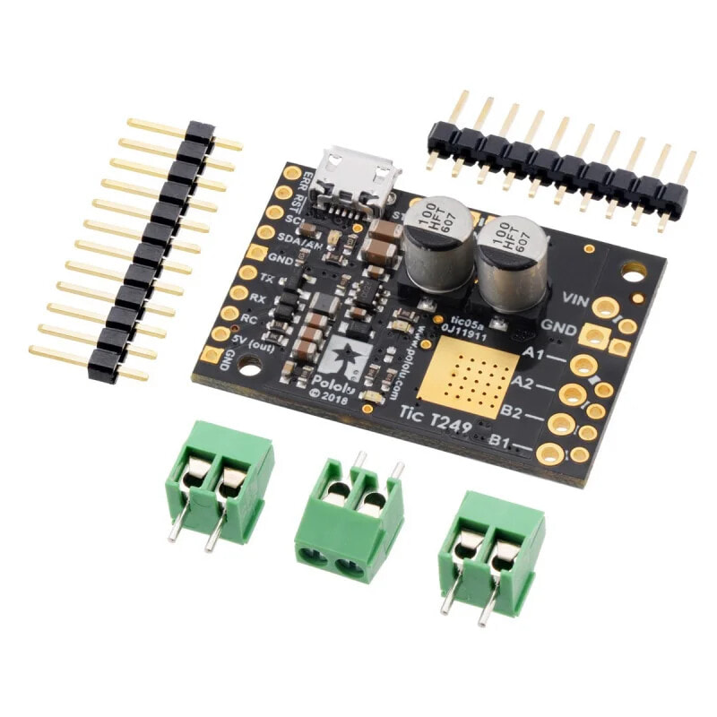
- Self-assembly kit
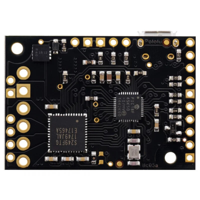
- Stepper motor controller module TB67S249FTG
- Goldpin slats
- Screw connections
- Manufacturer's website - Polol #3139
- Driver for Windows
- Windows Driver Installation Manual
- Motor connection instructions
- TB67S249FTG system documentation