TB67H420FTG Dual/Single Motor Driver Carrier- Pololu 2999
- Артикул:
- 42766896

Характеристики
Общие характеристики
- Напряжение до
- 10.0 V
- Напряжение от
- 4.2 V
Прочие свойства
- Бренд
- Pololu
Свойства
- Каналы
- 2
Энергопитание
- Сила тока
- 3.4 A
Описание
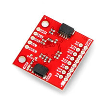
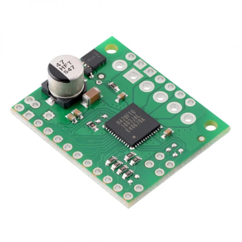
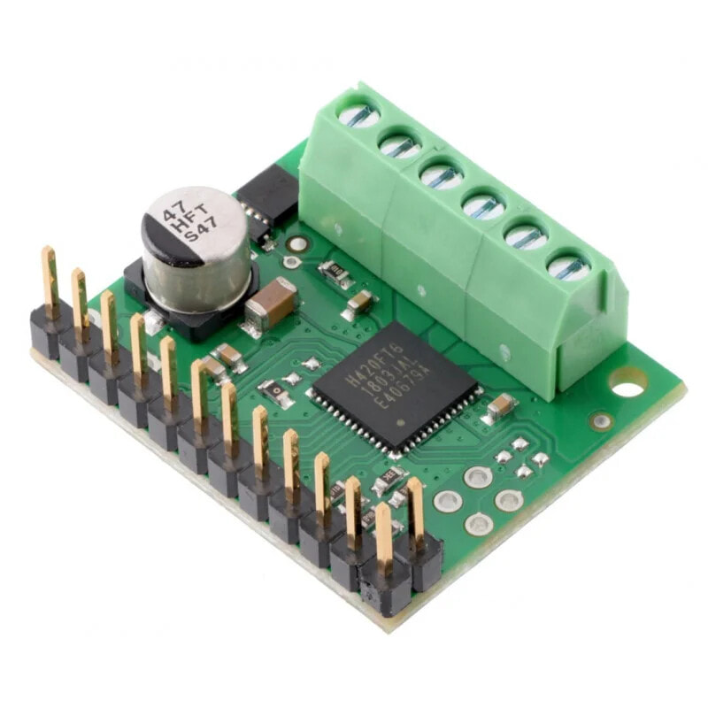
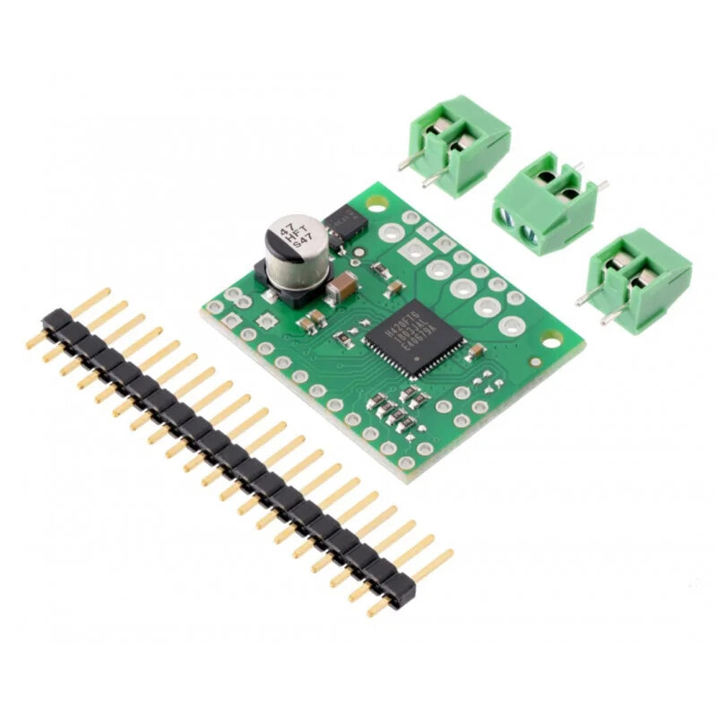
The module based on theTB67H420FTGchip allows you tocontrolup totwoDC motors. The motor can be supplied with voltagefrom 10 V to 47 Vat continuous current up to 1.7 A, momentary (for a few seconds) up to 4.5 A. We recommend reading theTB67H420FTGdocumentation before use.
Controller pinouts PIN Description Vin Motor supply voltage from 10 V to 47 V. It has protection against polarity change of supply voltage (up to 40 V). GND System ground potential. VM Output to provide power to the motor after reverse polarity protection. It can be used to power other components of the system. A+ Motor outputs A. To be connected for single channel mode. A- B+ B motor outputs. To be connected for single channel mode. B- VCC Adjustable 5 volt output. This pin gives access to the voltage from the TB67H420FTG internal regulator. The output should only be used for logic inputs as it can only provide a few milliamps. INA1Control input forA+.PWM can be applied to this pin (usually PWMA in the high state). Default state is low.
In single channel mode it controlsA+andA-.
INA2Control input forA-.PWM can be applied to this pin (usually PWMA in the high state). Default state is low.
In single channel mode, controlsB+andB-.
PWMAPWM input for channelA. Default state low.
In single channel mode, the PWM input.
INB1 Control input forB+.PWM can be applied to this pin (usually PWMB in high state). Default state is low. INB2 Control input forB-..PWM can be applied to this pin (usually PWMB in the high state). Default state is low. PWMB PWM input for channelB. Default state low. LO1Error diagnostics output. Goes low when an error occurs due to excessive current or temperature.
Default state is high.
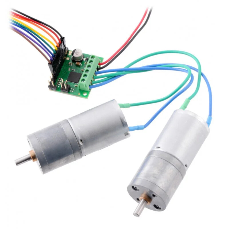
LO2 Error diagnostics output. Goes low when load or temperature fault occurs. Default is low. VREFA The output indicates the current threshold value for channelA.In single channel mode, outputs the current threshold value. VREFB The output indicates the current threshold value for channelB. TBLKAB Noise filter configuration pin for the constant current circuit. Default is low. Input should not be changed when the controller is powered. HBMODE Operating mode configuration input, High state for single channel mode, low state for dual channel trub.This input should not be changed when the controller is powered. Sensor connection with two motorsComplete truth table for TB67H420FTG
Input Output Operating mode PWMx INx1 INx2 x+ x- 0 0 0 Z ZFree running. Standby mode if all PWM and IN inputs are in the low state.
1 0 L LStop
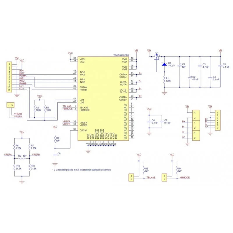
0 1 1 1 1 0 0 Z Z Free running 1 0 H L Forward speed 0 1 L H Reverse rotation 1 1 L L Stop DiagramThe system includes the controller and the necessary passive elements for its proper operation. Electronic circuit diagram is available on the drawing below.
Technical specifications of the controller from Pololu- Single / double channel motor controller
- Motor supply voltage: from 10 to 47 V
- Output current:
- 1.7 A (4.5 A instantaneous) in dual channel mode
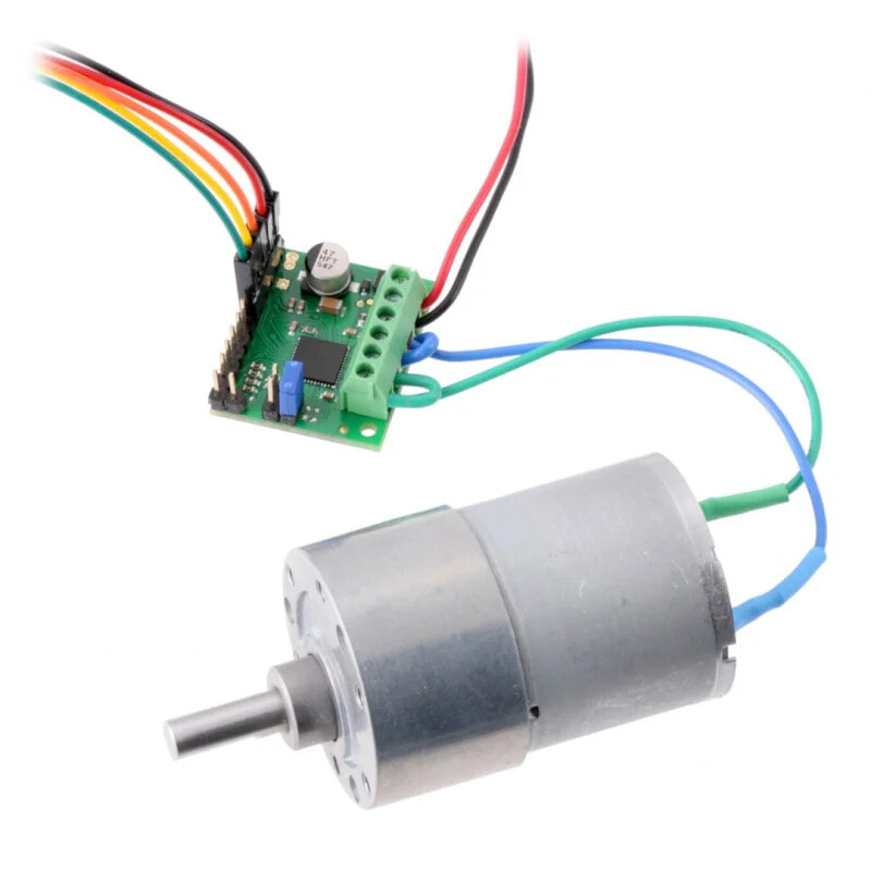
- 3.4 A (9 A instantaneous) in single channel mode
- Configurable current limiting thresholds of 4.5 A (dual channel mode) and 9 A (single channel mode), can be limited by additional resistors and voltage sources.
- No need for an additional logic power supply. Inputs are compatible with 3V and 5V
- Undervoltage, short-circuit and overheat protection
- Protects against reverse polarity of the supply voltage up to 40 V
- Dimensions: 25,4 x 30,5 mm
- Pololu #2999 manufacturer page
- Diagram of the module
- Documentation of the circuit