TB67H420FTG Dual/Single Motor Driver Carrier - Pololu 2997
Бестселлер
- Артикул:
- 42766810


-10%
9 086 AMD
Старая цена
Характеристики
- Напряжение до
- 4.5 V
- Напряжение от
- 28.0 V
Прочие свойства
- EAN
- 5904422318468
- Бренд
- Pololu
Свойства
- Каналы
- 1
Энергопитание
- Сила тока
- 2.5 A
Описание
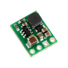
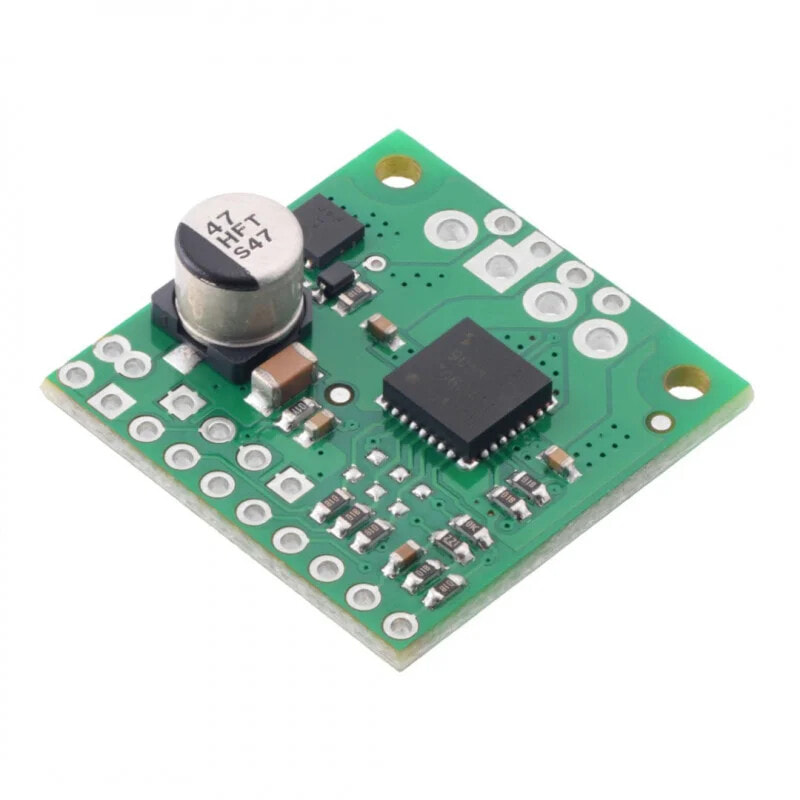
Product description: TB9051FTG - single channel motor controller 28V/2,6A - Pololu 2997
The modulebased on theTB9051FTGchip allows you tocontroloneDC motor. The motor can be supplied with voltagefrom 4.5V to 28Vwith continuous current up to 2.6A, momentary (for a few seconds) up to 5A. We recommend reading theTB9051FTGdocumentation before use.
Pinouts of one-channel controller PIN Description Vin Motor supply voltage from 4.5 V to 28 V. It has protection against polarity change of supply voltage. GND System ground potential. VM Output providing access to the motor power supply after reverse polarity protection. It can be used to power other components of the system. OUT1 Outputs - to connect the motor leads. OUT2 Outputs - to connect the motor leads. VCC Logic voltage - 5 V. OCC In case of overcurrent, the controller is switched off. By default in low state. If it is in high state it will automatically try to resume operation after a short time interval. EN When in the low state, the OUT1 and OUT2 outputs are set to the high impedance state. Inverted Inverted PWM can be applied to this pin(When EN is in the high state and PWM1 or PWM2 in the high state).Default is in the low state. ENB When it is in high state,OUT1 and OUT2 outputs are set to high impedance state.PWM can be applied to this pin(When ENB is in low state and PWM1 or PWM2 in high state).Default inhighstate. PWM1 Control input for OUT1. Default is low. PWM2 The control input for OUT2. Default low. OCM Current monitoring output, pin provides an analog feedback voltage of approximately 500 mV per amplifier. DIAG Error diagnostics output. goes low when errors occur or the controller is disabled by EN or ENB. Connecting the controller with a DC motorTable for PWM1 + PWM2 mode
Input Output Operation mode EN ENB PWM1 PWM2 OUT1 OUT2 1 0 PWM 0 PWM(H/L) LForward speed/brake speed
at the speed specified: PWM %
1 0 0 PWM L PWM(H/L)Reverse/Brake
at the speed specified: PWM %
1 0 0 0 L L Stop, outputs connected to ground 1 0 1 1 L L 0 X X X Z Z Free runningOutputs disconnected X 1 X X Z ZTable for PWM1 + PWM2 + EN mode
Input Output Operation mode EN ENB PWM1 PWM2 OUT1 OUT2 PWM 0 1 0 PWM(H/Z) PWM(L/Z)Forward speed/Free speed
at the speed specified: PWM %
0 1 PWM(L/Z) PWM(H/Z)Reverse speed/Free speed
at the speed specified: PWM %
0 X X X Z Z Free runningOutputs disconnected X 1 X X Z Z Scheme of the systemThe circuit includes thecontrollerand the necessary passive elements for its proper operation. The electronic schematic is available on the drawing below.
Technical specifications of the controller from Polol- Single-channelmotorcontroller
- Supply voltage of the motor: from 4.5 to 28 V
- Output current: 2.6 A (5 A momentary)
- Automatic current limitation function helps prevent overheating by gently reducing the voltage instead of abruptly shutting down
- Under-voltage, short-circuit and overheat protection
- Protects against polarity reversal of the supply voltage
- Dimensions: 25.4 x 25.4 mm
- Pololu #2997 manufacturer's website
- Diagram of the module
- Documentation of the circuit