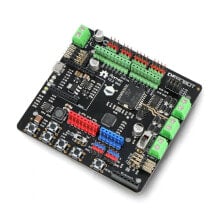
STSPIN220 Low-Voltage Stepper Motor Driver Carrier - Pololu 2876
- Артикул:
- 42766903


Характеристики
Общие характеристики
- Напряжение до
- 1,8 V
- Напряжение от
- 10 V
Прочие свойства
- Бренд
- Pololu
Свойства
- Каналы
- 1
Энергопитание
- Сила тока
- 1,1 A
Описание
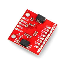
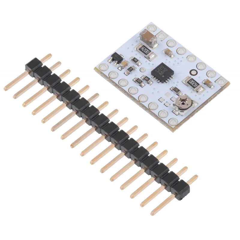
The system allows to control a singlebipolar stepper motor. It offers a wide range of step resolutions (from full to 1/256 steps). By setting the current-voltage parameters, higher step speeds are possible.
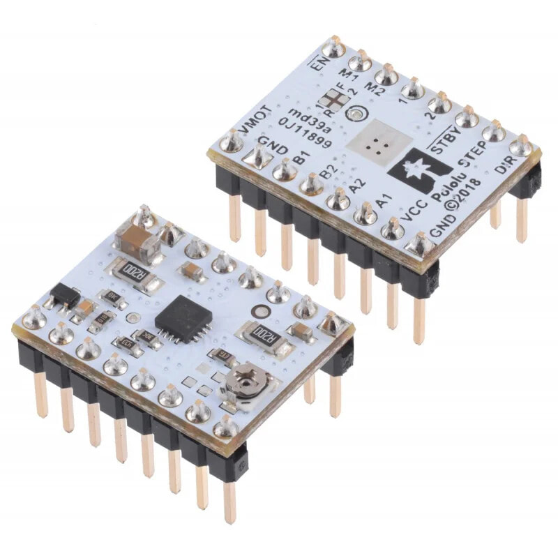
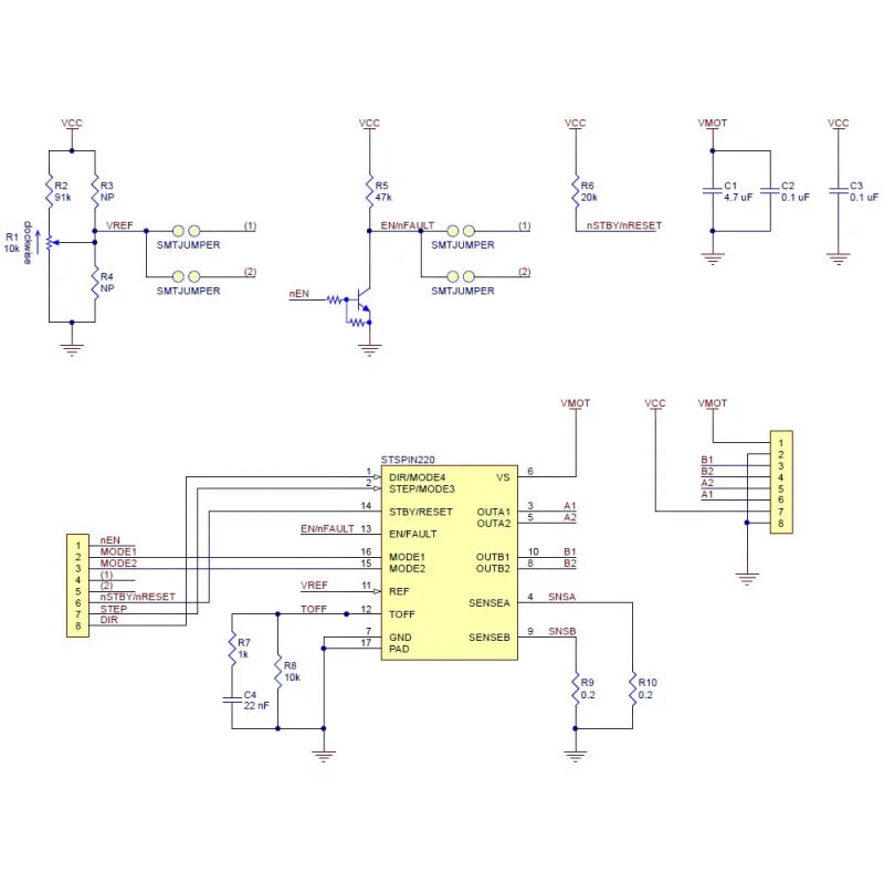
STSPIN220 works directly with 3.3 V and 5 V systems. The diagram below shows how to connect to a microcontroller.
The controller requires connection oflogical voltage (from 3 to 5 V)through VCC and GND outputs andmotor supplyvoltagefrom 1.8 Vto 10 V throughVIN and GND outputs. The power supplies should have appropriate decoupling capacitors located close to the board and should be able to deliver the expected currents. The system has protections against overheating, short circuit and exceeding the maximum current.
Polol STSPIN220 stepper motor controller specification- Minimum input voltage: 1,8 V
- Maximum input voltage: 10 V
- Continuous current per phase: 1.1 A
- Maximum current per phase: 1,3 A
- Minimum logical voltage: 1,6 V
- Maximum logical voltage: 5,5 V
- Microstep resolution: full, 1/2, 1/4, 1/8, 1/16, 1/32, 1/64, 1/128, 1/256
- Current limit control: potentiometer
- Soldering pins included
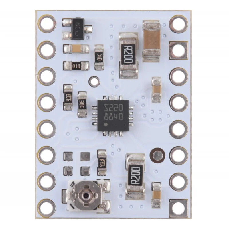
- Dimensions: 15.2 x 20.3 mm
- Weight: 1,4 g
The step size is selected using M0 - M4 inputs. The table below shows how to obtain the appropriate step resolution. The current limit must be set low enough for proper operation of the controller modes. Otherwise, the intermediate current levels will not be properly maintained and the motor will skip the microsteps.
MODE1 MODE2 MODE3 (STEP) MODE4 (DIR) Resolution Low Low Low Low Full step High Low High Low Half step Low High Low High 1/4 step High High High Low 1/8th step High Low High High 1/8th step High High High High step 1/16 Low High Low Low 1/32 step Low Low Low High 1/32 step (1) High High Low High 1 / 64 step Low High High High 1/64th step High Low Low Low 1/128 step Low Low High Low 1/128 step (1) High High Low Low 1/256 step Low High High Low 1/256 step High Low Low High 1/256 step Low Low High High 1/256 step (1)(1) Maintaining low states on the inputs MODE1 and MODE2 after configuring the step resolution forces the controller to full step mode instead of the selected configuration.
STSPIN220 has 2 different inputs to control power, STBY /RESET and EN/FAULTstates:
- low state on STBY pin: the controller enters low power mode, turns off the motor outputs and resets the translation table. Default high state on the STBY pin
- the low state on the ENABLE pin turns on the motor by default
STSPIN supports active pad limitation for high jumping speeds. One way to set the current limit is to set the controller to full step mode and measure the current flowing through a single motor coil without STEP input timing. The measured current will be equal to the current limit.
Current limit = VREF x 5
Attention!
The coil current may be very different from the power supply current. When setting the current limit, use the current measured at the power supply.
If the controller operates in full crow mode, both coils will always be on and limited to 100% of the current setting.
If the controller operates in one of the microcontrol modes, the current flowing through the coils will change with each step from 0% to 100% of the set limit.
Useful links- The manufacturer's website: Polol #2876
- STSPIN220 documentation
- Diagram