Step-Up/Step-Down Voltage Regulator S9V11MA - 2,5-9V 1,5A - Pololu 2869
- Артикул:
- 47399445


Характеристики
- Напряжение до
- 2.0 V
- Стабилизатор - Тип
- step-up/down
- Стабилизатор - Тип 2
- switching
- Выходное напряжение от
- 2.5 V
Вес и размеры
- Длина
- 15 mm
- Высота
- 3 mm
- Ширина
- 12 mm
Общие характеристики
- Напряжение от
- 16.0 V
- Выходное напряжение до
- 9.5 V
Прочие свойства
- Бренд
- Pololu
Энергопитание
- Сила тока
- 1.5 A
Описание
- Input voltage: from 3 V to 16 V
- Maximum output current: 1.5 A
- Resting current: 1 mA
- Output voltage: adjustable from 2.5 V to 9 V
- Short circuit and over temperature protection
- Dimensions: 15 x 13 x 6 mm
- Weight: 0.8 g (without connectors)
The converteris used to supply circuits with voltage from 2.5V to 9V. The circuit has a wide range of input voltages, which makes it ideal for battery-powered designs. Application of S9V11MA ensuresstability of power supplyduring the entire cycle of battery discharge. In order to increase reliability, the module is equipped with short-circuit protection and automatic power cut-off when the permissible operating temperature is exceeded.
We also offer a set to build asmartphone charger with on-line manual.
In set you will find goldpins for individual soldering.
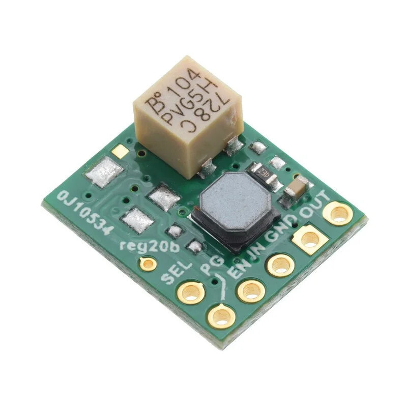
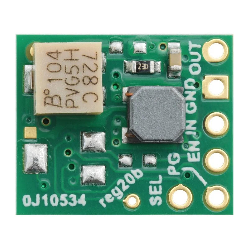
How to useThe module is very simple to use, it has three basic leads:
- VIN- input voltage from 3 V to 16 V. With lower voltage module will not turn on, higher can damage the chip.
- GND- Ground of the system.
- VOUT- output voltage from 2.5 V to 9 V.
Additional pins:
- EN- Enable input. Enables the circuit when the voltage is over 0,8 V. It is connected through voltage divider withVIN, so it cuts off the power at VIN below the set value.
- PG- voltage quality indicator. An open-drain type output, it sets low when the power drops below 90% of the nominal voltage, also when theENpin is in the low state. Returns to the high state when the mod 95 % is exceeded. Has high impedance, requires a pull-up resistor.
- SEL- not used
- Potentiometer for changing the output voltage
The acceptable input voltage range is from 3 V to 16 V. The regulator will not turn on at a lower value. A higher voltage may damage the circuit.
The connectors are properly signed on the board.The pinout is 2.54 mm (goldpin connectors). The module can be plugged into thecontactboard, connected bywiresor soldered into a dedicated PCB.
Output voltage settingOutput voltage is regulated by a built-in potentiometer. Turning clockwise increases the output voltage, which should be measured with a meter.
The voltage can be set below 2.5 V and above 9 V, but the device may then operate unstably. We recommend using the range specified by the manufacturer. Voltage may be 3% higher with little or no load. It may also drop depending on the current draw, especially when the input voltage is lower than the output voltage. However, it should be within 5% of the error.
Output CurrentThe maximum current that can flow through the circuit depends on the value of the input voltage. This relationship is shown in the graph below:
Maximum output current as a function of input voltage.
EfficiencyThis parameter is especially important with battery power supply, when it is important for the system to work as long as possible on a single charge. The efficiency of the converter depends on the current flowing and the input voltage (graph below). On average, it is between 85% and 95%, which allows to use practically the maximum energy from the battery.
The efficiency of the converter depending on the current consumed.
Voltage jumps (pins)In electronic circuits, the starting current may cause so-called spikes, sudden voltage jumps to a value above a set level. If the amplitude of the spikes exceeds the regulator's allowable value, the regulator can be destroyed. Therefore, if the circuit will be supplied with voltage above 9 V or the load will have high inductance, we recommend soldering a capacitor of 33 µF / 20 V or higher as close as possible to the circuit between VIN and GND.
Useful links- Manufacturer's website - Pololu #2869
- Module dimensions