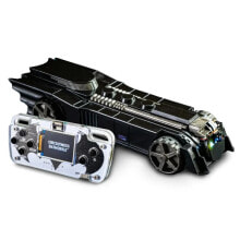
Set of magnetic encoders for Pololu micro motors (compatible with HPCB) 2.7-18V - 2 pcs - Pololu 3081
- Артикул:
- 47398251

Характеристики
Прочие свойства
- Бренд
- Pololu
Описание
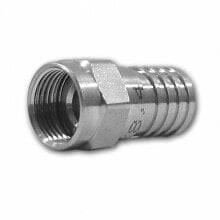
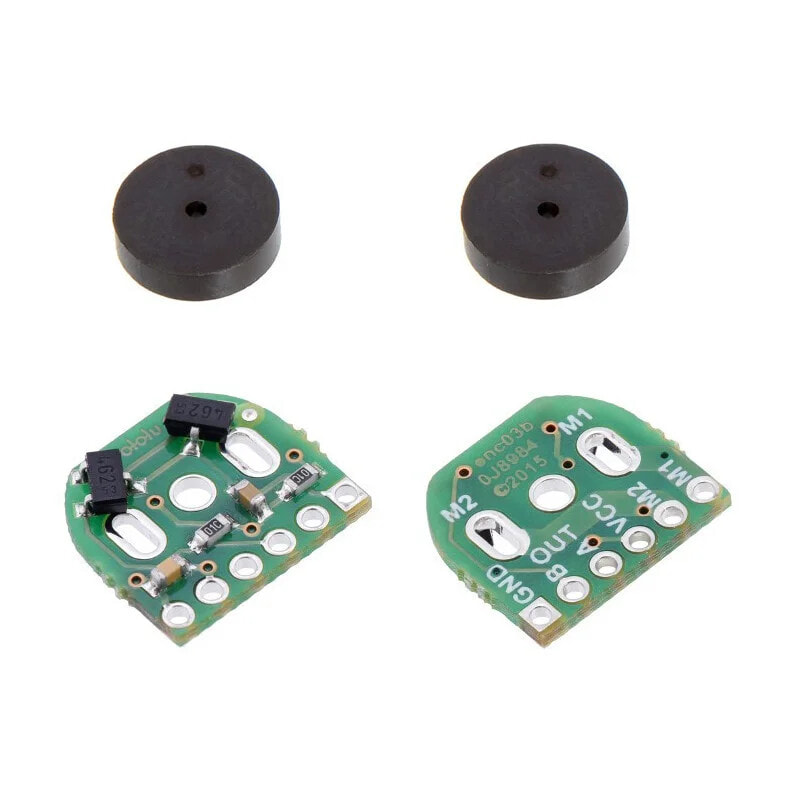
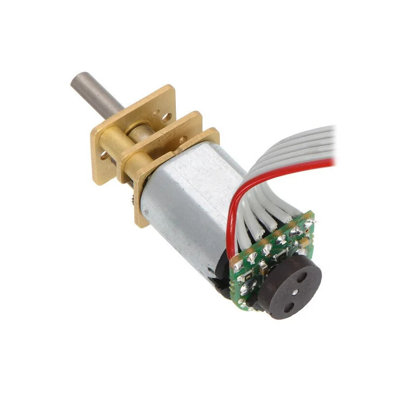
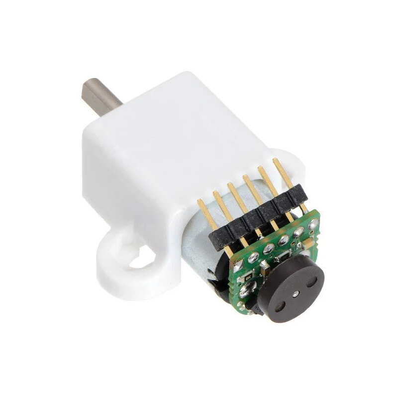
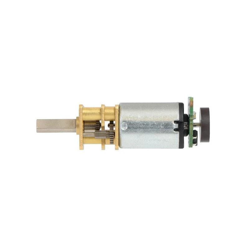
A pair of optical quadrature sensors, designed for installation in micro motors from Pololu from the micro series with bilateral shaft. The set consists of two boards with integrated sensors that use the Hall effect and two impellers with magnets. The set allows to obtain a resolution of 12 impulses per revolution, it is powered with the voltage ranging from 2.7 V to 18 V.
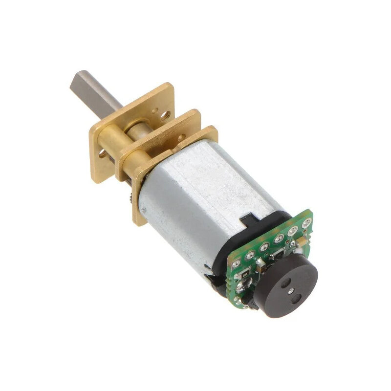
The sensors only work with thePololu micro motorsequipped with biliteral, extended shaft.
This version is also suitable for the latest engines from seriesHPCB with double-sided shaft.
Operating principle of the encoders
Specification- Supply voltage: from 2.7 V to 18 V
- Resolution: 12 impulses per revolution *
- Dimensions: 10.6 x 11.6 mm
- Weight: 1 g (without connectors)
- 2 x board with Hall sensors
- 2 x impeller with magnets
* The given resolution is the number of impulses per revolution of the engine. To count the impulses per revolution of the output shaft (wheel), multiply the specified number by the selected position. For example, for engine with the 30:1 gearing with the mounted five blades, the resolution will be: 20 * 30 = 600 pulses per revolution of the output shaft with gear.
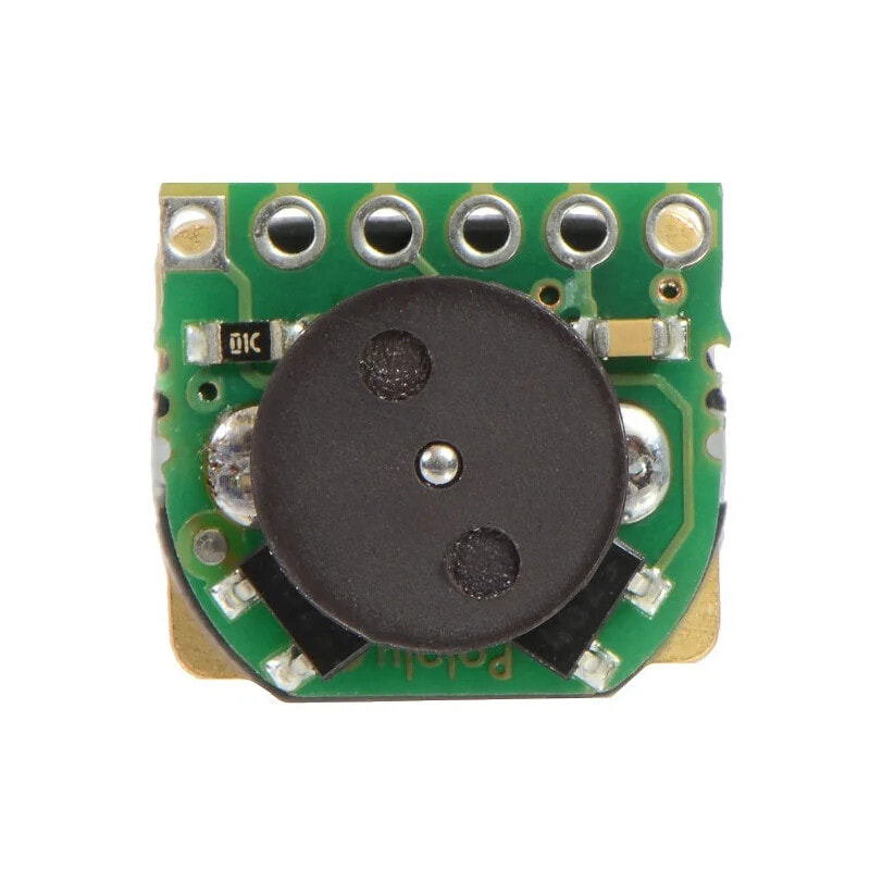
The size of the main board.
Installation and connectionThe board with sensors are designed for direct soldering on the power pins at the rear of the engine. The corresponding alignment of the module is the key to receiving the output signal of the high quality. One of the ways of the board installation, is to solder one end, then the align the module and solder the second pin. It is necessary to avoid prolonged heating of the pins of the engine as it may damage the plastic case.
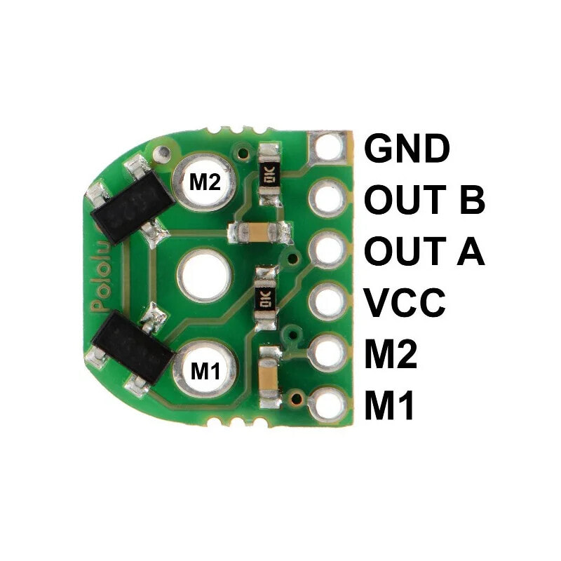
The distribution of the pins of the main board.
The mounting holes of the module are simultaneously power pins of the motor, connected to the M1 and M2 pins. OUT1, OUT2 pins are the quadrature outputs. Sensor's power supply must be connected between pins VCC and GND. Pins are applied to the board that have a distance of 2 mm which provides the connection with a suitable multicore tape.
When the module is properly soldered, on an extended shaft must be applied the impeller with magnets. The distance between the board and the impeller, doesn't affect the signal quality.
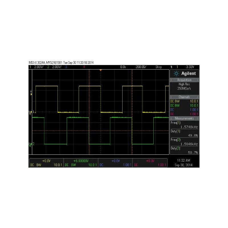
Oscillogram of the signal from the encoders.
Useful links
- Manufacturer's website - Pololu #3081
- Documentation of the used sensor TLE4946-2K
- Diagram of the module