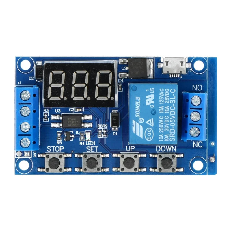
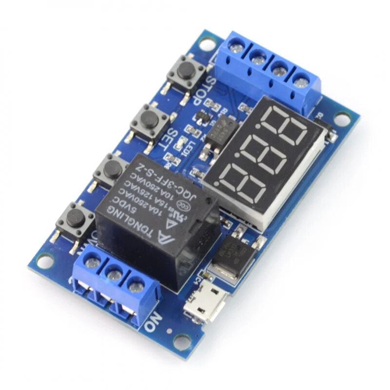
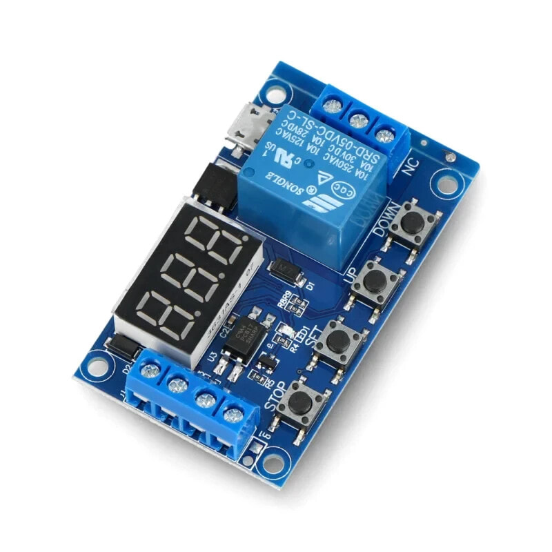
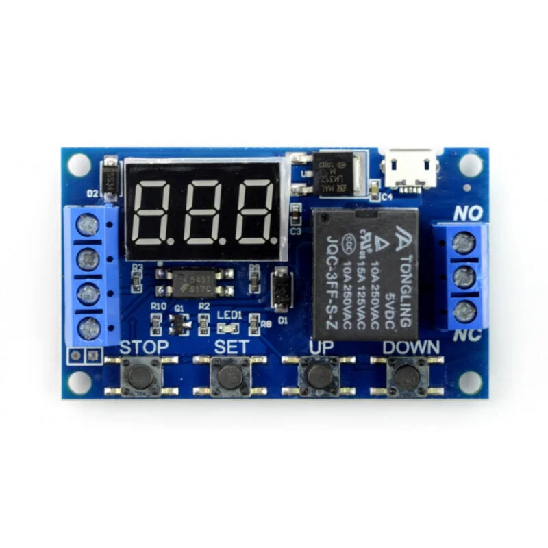
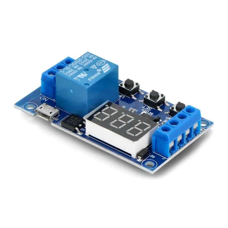
Relay module 1 channel with delay - 10A / 250VAC contacts - 5 V coil
Бестселлер
- Артикул:
- 42766379


2 428 AMD
Характеристики
Прочие свойства
- Бренд
- OEM
Свойства
- Каналы
- 1
- Подключение
- Digital I / O
Описание
Specification
- VCC supply voltage: 6 V to 30 V
- Trigger input voltage: 3 V to 24 V
- The switching of the status of the relay through the high status
- Relay SRD-05VDC-SL-C (documentation)
- Coil voltage: 5 V
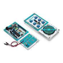
- 4 functional buttons
- Screw connectors as well as microUSB connectors
- It has optoinsulation and protection from reverse connection
- Contact options for resistive loads:
- 125 VAC / 10 A
- 250 V AC / 10 A
- 28 VDC / 10 A
- Board sizes: 65 x 38 mm
* Maximum contact voltage depends on the type of load - details in the documentation, tab. 7. Contact Rating.
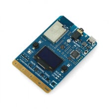
DescriptionThe module is equipped with relay SRD-05 with a coil powered with a voltage of 5 V. The system allows you to control actuators using microcontroller ports or any development set. The relay is equipped with a delay system operating in the range from 0.1 sec to 999 min providing a switch-on delay, turn-off delay,cyclical operation and the action during the hold.
Modes of operation
- P1.1: activation with the Trigger signal, it is off after the OP time. Indicating the signal again doesn't work.
- P1.2: activation with the Trigger signal, it is off after the OP time. Indicating the signal again starts counting from the beginning.
- P1.3: activation with the Trigger signal, it is off after the OP time. Indicating the signal again immediately turns off the relay.
- P-2: activation with the Trigger signal with a CL delay. It is switched off after OP time.
- P3.1: activation with the Trigger signal, it is off after the OP time. Then, after the CL delay time, is switched on again. The number of cycles is set by the LOP parameter.
- P3.2: activation without the Trigger signal, it is off after the OP time. Then, after the CL delay time, is switched on again. The number of cycles is set by the LOP parameter.
- P-4: the hold function. Relay operates during the hold of the Trigger signal. After disabling, it turns itself off after the time set by the OP parameter.
- After turning on the power, press and hold the SET button for 2 seconds. After relasing it, you can select the operation mode from P1.1 to P-4 using the buttons UP and DOWN.
- The mode is selected by briefly pressing the SET button
- Then, set the parameters of the delays:
- OP: turn-on time
- CL: time-off time
- LOP: the number of cycles
- While in the time setup mode, the STOP button allows you to select the unit. On the display, you should pay attention to the dot:
- XXX.: dot in the last place, the range from 1 sec to 999 sec
- XX.X: dot in the penultimate place, the range from 0.1 sec to 99.9 sec
- X. X. X.: three dots, range from 1 min to 999 min.
- After setting the parameters, press and hold SET button for 2 seconds. The name of the mode will begin to flash and then, the screen will return to the home screen and display 000.
- Pressing the STOP button on the home screen can pernamently disable the OFF relay. At the ON status, it works according to the set mode.
- Long hold of the STOP button, allows you to enter the device into sleep mode:
- C-P: sleep mode, after 5 minutes without pressing, the display turns off, the relay is working fine
- Oh-d: normal mode, the display is always on
Connection
The module has seven pins described in the following table:
PIN Description