MinIMU-9 v5 9DOF - accelerometer, gyroscope and magnetometer I2C - Pololu 2738
- Артикул:
- 47398157


Характеристики
Прочие свойства
- Бренд
- Pololu
Описание
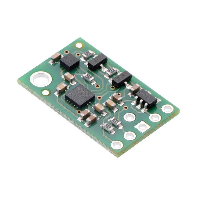
Module, using a 3-axis accelerometer, a magnetometer and a gyroscope, allows to measure nine independent values: acceleration, magnetic field and angular velocity - each in three axes. Knowledge of these values allows to find the object in 3D space. The popular I2C bus (TWI) is for communication with the central unit.
The kit includesthe goldpin connectorsfor self-assembly.
The module has a built-in voltage regulator and all necessary passive components. The leads are popular goldpin connectors for connecting the sensor viawiresor for directly attaching to breadboard.
Specification
- Supply voltage: 2.5 V - 5.5 V
- Current consumption: 5 mA
- Built-in voltage regulator
- Built-in voltage converter to the bus line I2C(the system works with voltages of 5 V and 3.3 V)
- Three axes: X, Y, Z
- Communication interface: I2C (TWI) Fast 400 kHz
- Resolution:
- Accelerometer: 16 bits
- Gyroscope: 16-bits
- Magnetometer: 16 bits
- Measuring ranges (configurable):
- Accelerometer: ± 2, ± 4, ± 8, ± 16 g
- Gyroscope: ± 125, ± 245, ± 500, ± 1000, ± 2000 °/s
- Magnetometer:, ± 4, ± 8, ± 12, ± 16 gauss
- The kit includes the strip goldpin for self-soldering
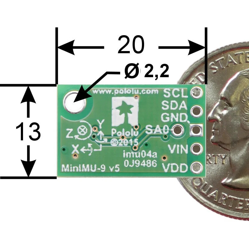
- Size: 20 x 13 x 3 mm
- Weight: 0,7 g (without connectors)
This kit includes the goldpin connectors for self-assembly.
MinImu-9 v5. vs MinImu-9 v3
In relation to the previous version, the MinImu-9 v5 has a new 3-axis MEMS sensors from the company ST - gyroscope and accelerometer LSM6DS33 (documentation) and magnetometer LIS3MDL (documentation). These sensors have higher precision and provides improved stability of measurement from its predecessors. New magnetometer allows to measure in a wider range - up to 16 GS. The distribution of leads is fully compatible with v3 but changed were the sample programs and libraries for Arduino.
The product is compatible with Arduino
A library for user of moduleArduino:
- LSM6DS33 Arduino library
- LIS3MDL Arduino library
Leads
The sensor has five leads for mounting goldpin connectors - 2.54 mm pitch (included in the kit for self soldering).
PIN Description SCL Clock line of the I2C bus. High, equal state is equal to the voltage VIN. Low GND. SDA The data line of the I2C bus. High, equal state is equal to the voltage VIN. Low GND. GND The potential of the mass of the system. VIN Supply voltage from 2.5 V to 5.5 V. VDD In the case where the voltage is higher than 3.3 V, the lead can be the output voltage 3.3 V with output current up to 150mA. When the supply voltage is in the range of 2.5 V - 3.3 V, you should connect it to VDD lead SA0
Input to change I2C addressing in accordance with the table below. By default, in the high state through a resistor of 10kΩ.Pin works with a voltage of 3.3 V, connecting 5 V can permanently damage the chip.
Addressing I2C
Accelerometer, magnetometer and gyroscope in a module MinImu-9, have 7-bit adresses. Mounted respectively on:
Sensor
Address
by default
Address
SA0 in low state
LSM6DS33
the accelerometer and gyroscope
1101011b 1101010bLIS3MD
magnetometer
0011110b 0011100bDimensions
The system is insmall size, its contour fits in a rectangle of a size: 20 x 13 mm. For mounting, use the hole with an inner diameter of 2.2 mm.
First runAll of the information required for start and operation of the sensor, is given inthe documentation. Below, we present selected important tips:
- Gyroscope, accelerometer and magnetometer are disabled by default, they must be run by setting the appropriate bits in the configuration registers
- You can read or send multiple commands in one I2C command. To do this, set the oldest bit of the address and thus, unlocking an auto-increment.
- Detailed information is available in the documentation for the individual sensors:LSM6DS33andLIS3MDL
Useful links
- The website of the manufacturer Pololu 2738
- Arduino library for the module LIS3MDL
- Arduino library for the module LSM6DS33
- Diagram of the module MinImu9 v5
- System documentationLIS3MDL
- System documentation LSM6DS33