LSM6DSO32 6DoF IMU - 3-axis accelerometer and gyroscope - Adafruit 4692
- Артикул:
- 53916363


Характеристики
- UC - I2C
- yes
- Напряжение от
- 5.0 V
- Напряжение до
- 3.0 V
- Интерфейс UC - SPI
- yes
Прочие свойства
- EAN
- 5904422378950
- Бренд
- Adafruit
- Тип датчика
- accelerometer, gyroscope
Описание
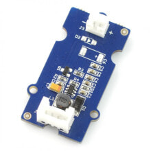
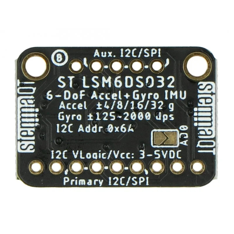
The6DoF LSM6DSO32is a module of theAdafruit3-axisaccelerometerand 3-axisgyroscope. It is used to measurelinear accelerationwithin± 4 / ± 8 / ± 16 / ± 32 gat an update frequency of 1,6 Hz to 6,7 kHz andangular velocity within± 125 / ± 250 / ± 500 / ± 1000 / ± 2000 dpsat 12,5 Hz to 6,7 kHz. For connection to the main module it usesgoldpinconnectors (included in the kit) or wires terminated with STEMMA QT orQwiicplug (available for purchase separately in our shop). The sensor communicates via theI2CandSPIinterface and can be used with devices poweredfrom 3 V to 5 V.
Product compatible withArduino
In order to facilitate work with the module, the manufacturer has prepareduser guideand a samplecodeforArduino IDE.
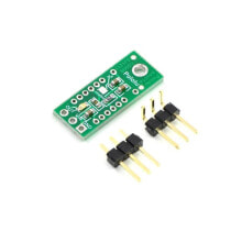
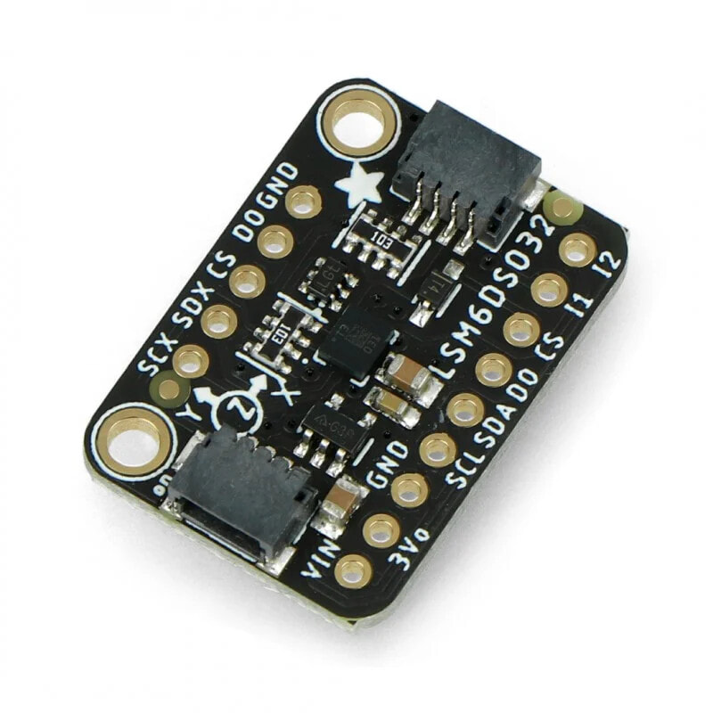
Description of module outputsThe sensor module is equipped with specialleadsto which the suppliedgoldpinconnectors (2.54 mm raster) must be soldered. Less complicated connection is provided by two inputs for STEMMA QT /Qwiicconnectors on the sensor board. They can be purchased separately in our shop. The description of the outputs can be found in the table below. Detailed information about this can be found inthe user guide.
The 6DoF sensor with accelerometer and a gyroscope.
Pin Description SCX, SDX, CS, TO Pins for advanced users are used to connect the sensor to another. VIN Pin power supply from 3 V to 5 V. 3Vo Output voltage 3.3 V with 100 mA capacity. GND The weight of the system. SCL I2C communication interface clock line. SDA I2C communication interface data line. DO SPI bus data output. CS Chip Select. It should be in a low state for SPI.INT1
INT2
Main interruption pins. They can be configured to go to a low state when new conditions occur, e.g. new measurement data. See thedocumentationfor more information. Technical specifications- Supply voltage: 3 V to 5 V
- Communication: SPI / I2C
- Connector type:
- Bilateral Qwiic
- Goldpin - raster 2.54 mm
- Accelerometer:
- 3 axes: X, Y, Z
- Scope: ± 4 / ± 8 / ± 16 / ± 32 g
- Frequency: 1.6 Hz to 6.7 kHz
- Gyroscope:
- 3 axes: X, Y, Z
- Scope: ± 125 / ± 250 / ± 500 / ± 1000 / ± 2000 dps
- Frequency: 12.5 Hz to 6.7 kHz
- Communication interface: I2C / SPI
- I2C interface address: 0x6A
The set includes dedicated 2.54 mm goldpin raster connectors.
Set contents- MPM3610 converter module
- Goldpin raster connectors 2.54 mm
- The manufacturer's website: Adafruit 4692
- User guide
- Sample program code for Arduino IDE
- Technical Documentation LSM6DSOX
- Technical Documentation ISM330DHCX
- Technical Documentation LSM6DSO32