Module LTE/GSM - u-GSM shield v2.19 EG91E - for Arduino and Raspberry Pi - u.FL connector
- Артикул:
- 42763942


Характеристики
Прочие свойства
- Бренд
- Itbrain Power
Описание
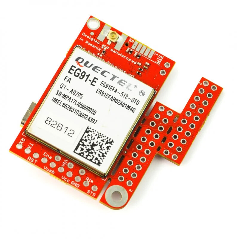
Module compatible with Arduino, Raspberry Pi (version 3B+, 3B, 2B, B+ and A+) and BeagleBone Black, which enables communication in LTE / GSM CAT1 standard. It allows to make voice calls and send SMS messages. On the board there are: SIM card connector, charging module for Li-Pol / Li-Ion battery and RESET button. It has connectors for GSM u.FL antennas.
Component layout on the u-GSM shield board.
The chip works with Arduino Uno using the following pins:
Pin Arduino Description GSM RX D3 Communication via serial interface. GSM TX D2 Communication via serial interface. RESET D6 Reset of the GSM chip. Ena D7 Control voltage of GSM chip (On/Off). VIN (5 V LiPol) 5 V5 V power supply. Details of connection in case of LiPol batteries are available in manufacturer's manual.
GND
GND System ground.STATUS
D5 Status pinout. Connecting LTE/GSM module to Raspberry PiThe module has special breakout connectors that allow direct plugging into the GPIO connectors of the Raspberry Pi or BeagleBone Black.
In order to run the module with Raspberry Pi the following connections need to be made:
Pin RPi Description GSM RX 10Communication via serial interface, (not connected for USB communication).
GSM TX 08Communication via serial interface (not connected when using USB).
RESET 18 GSM system reset. ON / OFF 16 GSM system power voltage control (On/Off). VIN (5 V LiPol) 02/04 Supply voltage 5 V.GND
04/14 GND of the chip. STATUS 12 Status pinout.Detailed description of the module can be found in the user guide in parts one and two and on the manufacturer's website.
- Controller: Quectel EG91E
- Supported standards: LTE / M2M CAT1
- Frequencies:
- FDD LTE: B1 / B3 / B7 / B8 / B20 / B28A
- WCDMA: B1 / B5 / B8
- GSM: B1 / B8
- Speeds:
- LTE-FDD: up to 10 Mb/s (DL) / up to 10 Mb/s (UL)
- DC-HSDPA: up to 42 Mbps (DL) / HSUPA up to 5.76 Mbps (UL)
- WCDMA: up to 384 Kbps (DL) / up to 384 Kbps (UL)
- EDGE/GPRS: up to max. 296 Kbps (DL), max. 236.8 Kbps (UL) / max. 107 Kbps (DL), max. 85.6 Kbps (UL)
- Nano SIM / micro SIM connector
- Antenna connectors u.FL
- Built-in USB-UART converter (USB connector can be used to power the module)
- Automatic selection of logic levels from 3 V to 5 V
- Reset button
- Works with Arduino, Raspberry Pi and BeagleBone Black along with manufacturer's sample codes
- Two mounting holes with diameter: 2.5mm
- Board dimensions: 45 x 27 mm
- Manufacturer homepage
- User guide 1
- User'sGuide 2 - interfacing with RaspberryPi
- User's Guide 3 - interfacing with BeagleBone Black
- u-GSM modules presentation
- Quectel EG91E module documentation